Description du produit
Description du produit
Description du produit
SWC BH Cardan Shaft Basic Parameter And Main Dimension
Cardan shaft is widely used in rolling mill, punch, straightener, crusher, ship drive, paper making equipment, common machinery, water pump equipment, test bench, and other mechanical applications.
Advantage:
1. Low life-cycle costs and long service life;
2. Increase productivity;
3. Professional and innovative solutions;
4. Reduce carbon dioxide emissions, and environmental protection;
5. High torque capacity even at large deflection angles;
6. Easy to move and run smoothly;
Detailed Photos
Paramètres du produit
| Model | Tn kN • m |
T. |
p (.) |
LS mm |
Lmin | Size mm |
I kg. m2 | m kg |
|||||||||||
| Di js11 |
d2 H7 |
Da | Lm | n-d | k | t | b h9 |
g | Lmin | 100mm | Lmin | 100mm | |||||||
| SWC58BH | 58 | 0.15 | 0.075 | ≤22 | 35 | 325 | 47 | 30 | 38 | 35 | 4-5 | 3.5 | 1.5 | – | – | – | – | 2.2 | – |
| SWC65BH | 65 | 0.25 | 0.125 | ≤22 | 40 | 360 | 52 | 35 | 42 | 46 | 4-6 | 4.5 | 1.7 | – | – | – | – | 3.0 | – |
| SWC75BH | 75 | 0.50 | 0.25 | ≤22 | 40 | 395 | 62 | 42 | 50 | 58 | 6-6 | 5.5 | 2.0 | – | – | – | – | 5.0 | – |
| SWC90BH | 90 | 1.0 | 0.50 | ≤22 | 45 | 435 | 74.5 | 47 | 54 | 58 | 4-8 | 6.0 | 2.5 | – | – | – | – | 6.6 | – |
| SWC100BH | 100 | 1.5 | 0.75 | ≤25 | 55 | 390 | 84 | 57 | 60 | 58 | 6-9 | 7 | 2.5 | – | – | 0.0044 | 0.00019 | 6.1 | 0.35 |
| SWC120BH | 120 | 2.5 | 1.25 | ≤25 | 80 | 485 | 102 | 75 | 70 | 68 | 8-11 | 8 | 2.5 | – | – | 0.5719 | 0.00044 | 10.8 | 0.55 |
| SWC150BH | 150 | 5 | 2.5 | ≤25 | 80 | 590 | 13.0 | 90 | 89 | 80 | 8-13 | 10 | 3.0 | – | – | 0.0423 | 0.00157 | 24.5 | 0.85 |
| SWC160BH | 160 | 10 | 5 | ≤25 | 80 | 660 | 137 | 100 | 95 | 110 | 8-15 | 15 | 3.0 | 20 | 12 | 0.1450 | 0.0060 | 68 | 1.72 |
| SWC180BH | 180 | 20 | 10 | ≤25 | 100 | 810 | 155 | 105 | 114 | 130 | 8-17 | 17 | 5.0 | 24 | 14 | 0.1750 | 0.0070 | 70 | 2.8 |
| SWC200BH | 200 | 32 | 16 | ≤15 | 110 | 860 | 170 | 120 | 127 | 135 | 8-17 | 19 | 5.0 | 28 | 16 | 0.3100 | 0.0130 | 86 | 3.6 |
| SWC225BH | 225 | 40 | 20 | ≤15 | 140 | 920 | 196 | 135 | 152 | 120 | 8-17 | 20 | 5.0 | 32 | 9.0 | 0.5380 | 0.5714 | 122 | 4.9 |
| SWC250BH | 250 | 63 | 31.5 | ≤15 | 140 | 1035 | 218 | 150 | 168 | 140 | 8-19 | 25 | 6.0 | 40 | 12.5 | 0.9660 | 0.5717 | 172 | 5.3 |
| SWC285BH | 285 | 90 | 45 | ≤15 | 140 | 1190 | 245 | 170 | 194 | 160 | 8-21 | 27 | 7.0 | 40 | 15.0 | 2.0110 | 0.571 | 263 | 6.3 |
| SWC315BH | 315 | 125 | 63 | ≤15 | 140 | 1315 | 280 | 185 | 219 | 180 | 10-23 | 32 | 8.0 | 40 | 15.0 | 3.6050 | 0.571 | 382 | 8.0 |
| SWC350BH | 350 | 180 | 90 | ≤15 | 150 | 1410 | 310 | 210 | 267 | 194 | 10-23 | 35 | 8.0 | 50 | 16.0 | 7.571 | 0.2219 | 582 | 15.0 |
| SWC390BH | 390 | 250 | 125 | ≤15 | 170 | 1590 | 345 | 235 | 267 | 215 | 10-25 | 40 | 8.0 | 70 | 18.0 | 12.164 | 0.2219 | 738 | 15.0 |
| SWC440BH | 440 | 355 | 180 | ≤15 | 190 | 1875 | 390 | 255 | 325 | 260 | 16-28 | 42 | 10 | 80 | 20.0 | 21.420 | 0.4744 | 1190 | 21.7 |
| SWC490BH | 490 | 500 | 250 | ≤15 | 190 | 1985 | 435 | 275 | 325 | 270 | 16-31 | 47 | 12 | 90 | 22.5 | 32.860 | 0.4744 | 1452 | 21.7 |
| SWC550BH | 550 | 710 | 355 | ≤15 | 240 | 2300 | 492 | 320 | 426 | 305 | 16-31 | 50 | 12 | 100 | 22.5 | 68.920 | 1.3570 | 2380 | 34 |
Emballage et expédition
Profil de l'entreprise
HangZhou CHINAMFG Machinery Manufacturing Co., Ltd. is a high-tech enterprise specializing in the design and manufacture of various types of coupling. There are 86 employees in our company, including 2 senior engineers and no fewer than 20 mechanical design and manufacture, heat treatment, welding, and other professionals.
Advanced and reasonable process, complete detection means. Our company actively introduces foreign advanced technology and equipment, on the basis of the condition, we make full use of the advantage and do more research and innovation. Strict to high quality and operate strictly in accordance with the ISO9000 quality certification system standard mode.
Our company supplies different kinds of products. High quality and reasonable price. We stick to the principle of “quality first, service first, continuous improvement and innovation to meet the customers” for the management and “zero defect, zero complaints” as the quality objective.
Our Services
1. Design Services
Our design team has experience in Cardan shafts relating to product design and development. If you have any needs for your new product or wish to make further improvements, we are here to offer our support.
2. Product Services
raw materials → Cutting → Forging →Rough machining →Shot blasting →Heat treatment →Testing →Fashioning →Cleaning→ Assembly→Packing→Shipping
3. Samples Procedure
We could develop the sample according to your requirement and amend the sample constantly to meet your need.
4. Research & Development
We usually research the new needs of the market and develop new models when there are new cars in the market.
5. Quality Control
Every step should be a particular test by Professional Staff according to the standard of ISO9001 and TS16949.
FAQ
Q 1: Are you a trading company or a manufacturer?
A: We are a professional manufacturer specializing in manufacturing
various series of couplings.
Q 2:Can you do OEM?
Yes, we can. We can do OEM & ODM for all customers with customized PDF or AI format artwork.
Q 3:How long is your delivery time?
Generally, it is 20-30 days if the goods are not in stock. It is according to quantity.
Q 4: Do you provide samples? Is it free or extra?
Yes, we could offer the sample but not for free. Actually, we have an excellent price principle, when you make the bulk order the cost of the sample will be deducted.
Q 5: How long is your warranty?
A: Our Warranty is 12 months under normal circumstances.
Q 6: What is the MOQ?
A: Usually our MOQ is 1pcs.
Q 7: Do you have inspection procedures for coupling?
A:100% self-inspection before packing.
Q 8: Can I have a visit to your factory before the order?
A: Sure, welcome to visit our factory.
Q 9: What’s your payment?
A:1) T/T.
♦Contact Us
Web: huadingcoupling
Add: No.11 HangZhou Road,Chengnan park,HangZhou City,ZheJiang Province,China
| Condition: | New |
|---|---|
| Color: | as Required |
| Certification: | ISO |
| Taper: | Universal Joint |
| Matériel: | Carbon Steel or as Required |
| Size: | Standard Size |
| Personnalisation : |
Disponible
| Demande personnalisée |
|---|
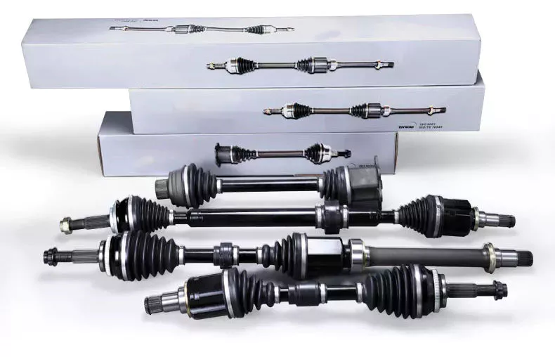
How do PTO shafts ensure efficient power transfer while maintaining safety?
PTO (Power Take-Off) shafts play a crucial role in ensuring efficient power transfer from a power source to driven machinery or equipment, while also maintaining safety. These shafts are designed with various features and mechanisms to optimize power transmission efficiency and mitigate potential hazards. Here’s a detailed explanation of how PTO shafts achieve efficient power transfer while prioritizing safety:
1. Mechanical Power Transmission: PTO shafts serve as mechanical linkages between the power source, typically a tractor or engine, and the driven machinery. They transmit rotational power from the power source to the equipment, enabling efficient transfer of energy. The mechanical design of PTO shafts, including their diameter, length, and material composition, is optimized to minimize power losses during transmission, ensuring that a significant portion of the power generated by the source is effectively delivered to the machinery.
2. Universal Joints and Flexible Couplings: PTO shafts are equipped with universal joints and flexible couplings that allow for angular misalignment and flexibility in movement. Universal joints accommodate variations in the alignment between the power source and the driven machinery, enabling smooth power transfer even when the two components are not perfectly aligned. Flexible couplings help to compensate for slight misalignments, reduce vibration, and prevent excessive stress on the shaft and connected components, thereby enhancing efficiency and reducing the risk of mechanical failure or damage.
3. Constant Velocity (CV) Joints: CV joints are often used in PTO shafts to maintain constant speed and torque transfer, particularly in applications where the driven machinery requires flexibility or operates at different angles. CV joints allow for smooth power transmission without significant fluctuations, even when the driven machinery is at an angle relative to the power source. By minimizing speed variations and power loss due to changing angles, CV joints contribute to efficient power transfer while ensuring consistent performance and reducing the likelihood of mechanical stress or premature wear.
4. Safety Guards and Shields: Safety is a paramount consideration in the design of PTO shafts. Protective guards and shields are installed to cover the rotating shaft and other moving parts. These guards act as physical barriers to prevent accidental contact with the rotating components, significantly reducing the risk of entanglement, injury, or damage. Safety guards are typically made of durable materials such as metal or plastic and are designed to allow the necessary movement for power transmission while providing adequate protection. Regular inspection and maintenance of these guards are crucial to ensure their effectiveness in maintaining safety.
5. Shear Bolt or Slip Clutch Mechanisms: PTO shafts often incorporate shear bolt or slip clutch mechanisms as safety features to protect the driveline components and prevent damage in case of excessive torque or sudden resistance. Shear bolts are designed to shear or break when the torque exceeds a predetermined threshold, disconnecting the PTO shaft from the power source. This helps prevent damage to the shaft, driven machinery, and power source. Slip clutches work similarly by allowing the PTO shaft to slip when excessive resistance is encountered, protecting the components from overload. These mechanisms act as safety measures to maintain the integrity of the PTO shaft and associated equipment while minimizing the risk of mechanical failures or accidents.
6. Compliance with Safety Standards: PTO shafts are designed and manufactured to comply with relevant safety standards and regulations. Manufacturers follow guidelines and requirements set by organizations such as the American Society of Agricultural and Biological Engineers (ASABE) or other regional safety authorities. Compliance with these standards ensures that PTO shafts meet specific safety criteria, including torque capacity, guard design, and other safety considerations. Users can rely on standardized PTO shafts that have undergone testing and certification, providing an additional layer of assurance regarding their safety and performance.
7. Operator Education and Training: To ensure safe and efficient operation, it is essential for operators to receive proper education and training on PTO shafts. Operators should be familiar with the specific safety features, maintenance requirements, and safe operating procedures for the PTO shafts used in their applications. This includes understanding the importance of using appropriate personal protective equipment, regularly inspecting the equipment for wear or damage, and following recommended maintenance schedules. Operator awareness and adherence to safety protocols significantly contribute to maintaining a safe working environment and maximizing the efficiency of power transfer.
In summary, PTO shafts ensure efficient power transfer while maintaining safety through their mechanical design, incorporation of universal joints and CV joints, installation of safety guards and shields, implementation of shear bolt or slip clutch mechanisms, compliance with safety standards, and operator education. By combining these features and practices, PTO shafts provide reliable and secure power transmission, minimizing power losses and potential risks associated with their operation.
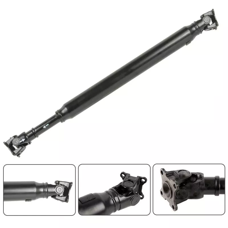
Existe-t-il des limitations ou des inconvénients liés aux arbres de prise de force ?
Bien que les arbres de prise de force (PDF) offrent de nombreux avantages en termes de transmission de puissance et de polyvalence, ils présentent également certaines limitations et certains inconvénients. Il est important de prendre en compte ces facteurs lors de l'utilisation d'arbres de PDF afin de garantir un fonctionnement sûr et efficace. Voici une explication détaillée de certaines limitations et inconvénients associés aux arbres de PDF :
1. Risques pour la sécurité : L'un des principaux problèmes liés aux arbres de prise de force (PDF) est le risque potentiel pour la sécurité. Ces arbres tournent à grande vitesse et peuvent présenter un danger important s'ils ne sont pas correctement protégés ou manipulés. Un contact accidentel avec un arbre de PDF exposé ou insuffisamment protégé peut entraîner des blessures graves, telles que l'enchevêtrement, l'amputation, voire le décès. Il est donc essentiel de respecter les consignes de sécurité, de mettre en place des protections adéquates et de veiller à ce que les opérateurs soient bien formés aux bonnes pratiques de manipulation afin de limiter ces risques.
2. Entretien et lubrification : Les arbres de prise de force nécessitent un entretien et une lubrification réguliers pour garantir des performances optimales et une longue durée de vie. Les pièces mobiles, telles que les joints de cardan et les cannelures, doivent être inspectées, nettoyées et lubrifiées aux intervalles recommandés. Négliger l'entretien peut entraîner une usure prématurée, une baisse d'efficacité et des pannes potentielles. Des pratiques d'entretien appropriées, incluant des inspections régulières et une lubrification en temps voulu, sont essentielles pour éviter ces problèmes.
3. Alignement et angles : L'efficacité du transfert de puissance dépend de l'alignement et des angles précis des arbres de prise de force. Un mauvais alignement ou des angles excessifs entre la source d'énergie et la machine entraînée peuvent engendrer une usure et une contrainte accrues sur les composants, conduisant à une défaillance prématurée. Il est donc important de veiller à un alignement et à un réglage des angles corrects, à l'aide de coulisseaux réglables ou d'autres moyens, afin de prévenir toute contrainte excessive sur l'arbre de prise de force et les équipements associés.
4. Limitations de longueur : Les arbres de prise de force (PDF) présentent des limitations de longueur maximale et minimale dues à des contraintes techniques. Leur conception télescopique permet un certain réglage, mais l'extension ou la rétraction de l'arbre reste limitée. Si la distance entre la source d'énergie et la machine entraînée dépasse la longueur maximale ou est inférieure à la longueur minimale de l'arbre de PDF, des solutions alternatives ou des modifications peuvent s'avérer nécessaires. Dans certains cas, des composants supplémentaires, tels que des rallonges d'arbre de transmission ou des réducteurs, peuvent être requis pour compenser cette distance.
5. Compatibilité : Bien que les fabricants s'efforcent d'assurer la compatibilité, trouver l'arbre de prise de force adapté à une configuration d'équipement spécifique peut s'avérer complexe. En effet, certains équipements peuvent présenter des exigences particulières en matière de dimensions des cannelures, de couples admissibles ou de méthodes de connexion, qui ne sont pas toujours disponibles ou compatibles avec les arbres de prise de force standard. Une personnalisation peut alors être nécessaire pour résoudre ces problèmes de compatibilité, ce qui peut engendrer des coûts supplémentaires ou des délais de livraison plus longs.
6. Bruit et vibrations : Les prises de force en fonctionnement peuvent générer un bruit et des vibrations importants, surtout à haut régime. Cela peut s'avérer gênant pour les opérateurs et nécessiter des mesures supplémentaires pour réduire le bruit ou amortir les vibrations. Des vibrations excessives peuvent également affecter les performances et la durée de vie de la prise de force et des équipements qui y sont raccordés. L'installation d'amortisseurs de vibrations ou l'utilisation d'accouplements flexibles peuvent contribuer à atténuer ces problèmes.
7. Limites de puissance : Les arbres de prise de force (PDF) ont des limites de puissance spécifiques liées à leur conception, leurs matériaux et leurs composants. Le dépassement de ces limites peut entraîner une usure prématurée, des défaillances de composants, voire la rupture de l'arbre. Il est essentiel de comprendre et de respecter les puissances nominales recommandées pour les arbres de PDF afin de garantir un fonctionnement sûr et fiable. Dans certains cas, il peut être nécessaire d'opter pour un arbre de PDF de plus grande capacité ou d'ajouter des composants de transmission de puissance pour répondre à des besoins en puissance supérieurs.
8. Installation et désinstallation complexes : L'installation et la dépose des arbres de prise de force peuvent s'avérer complexes, notamment dans les espaces restreints ou lors de la manipulation d'équipements lourds. Elles peuvent nécessiter l'alignement des cannelures, la mise en place des accouplements et le verrouillage des mécanismes. Des techniques d'installation ou de dépose incorrectes peuvent endommager l'arbre ou l'équipement associé. Une formation adéquate, la manipulation appropriée des équipements et le respect des consignes du fabricant sont essentiels pour simplifier et garantir l'installation et la dépose en toute sécurité des arbres de prise de force.
Malgré ces limitations et inconvénients, les arbres de prise de force restent des composants essentiels et largement utilisés pour la transmission de puissance dans divers secteurs industriels. En tenant compte de ces aspects et en appliquant des mesures de sécurité, des pratiques de maintenance et des procédures d'alignement appropriées, les inconvénients potentiels des arbres de prise de force peuvent être efficacement atténués, permettant ainsi un fonctionnement sûr et efficace.

What is a PTO shaft and how is it used in agricultural and industrial equipment?
A power take-off (PTO) shaft is a mechanical component used in agricultural and industrial equipment to transfer power from a power source, such as an engine or motor, to another machine or implement. It is a driveline shaft that transmits rotational power and torque, allowing the connected equipment to perform various tasks. PTO shafts are commonly used in agricultural machinery, such as tractors, as well as in industrial equipment, including generators, pumps, and construction machinery. Here’s a detailed explanation of what a PTO shaft is and how it is used:
Structure and Components: A typical PTO shaft consists of a hollow metal tube with universal joints at each end. The hollow tube allows the shaft to rotate freely, while the universal joints accommodate angular misalignments between the power source and the driven equipment. The universal joints consist of a cross-shaped yoke with needle bearings, providing flexibility and allowing the transmission of power at varying angles. Some PTO shafts may also include a telescopic section to adjust the length for different equipment setups or to accommodate varying distances between the power source and the driven machine.
Power Transfer: The primary function of a PTO shaft is to transfer power and torque from the power source to the driven equipment. The power source, typically an engine or motor, drives the PTO shaft through a mechanical connection, such as a gearbox or a clutch. As the power source rotates, it transmits rotational force to the PTO shaft. The PTO shaft, in turn, transfers this rotational power and torque to the driven equipment, enabling it to perform its intended function. The torque and rotational speed transmitted through the PTO shaft depend on the power source’s characteristics and the gear ratio or clutch engagement.
Agricultural Applications: In agriculture, PTO shafts are commonly used in tractors to power various implements and attachments. The PTO shaft is connected to the tractor’s power take-off, a rotating drive shaft located at the rear of the tractor. By engaging the PTO clutch, the tractor’s engine power is transferred through the PTO shaft to the attached implements. Agricultural machinery, such as mowers, balers, tillers, sprayers, and grain augers, often rely on PTO shafts to receive power for their operation. The PTO shaft allows the implements to be powered directly by the tractor’s engine, eliminating the need for separate power sources and increasing the versatility and efficiency of agricultural operations.
Industrial Applications: PTO shafts also find extensive use in various industrial applications. Industrial equipment, such as generators, pumps, compressors, and industrial mixers, often incorporate PTO shafts to receive power from engines or electric motors. The PTO shaft connects the power source to the driven equipment, allowing it to operate and perform its intended function. In construction machinery, PTO shafts can be found in equipment like concrete mixers, hydraulic hammers, and post hole diggers, enabling the transfer of power from the machinery’s engine to the specific attachment or tool being used.
Safety Considerations: It is important to note that PTO shafts can pose safety risks if not handled properly. The rotating shaft can cause serious injuries if operators come into contact with it while it is in operation. To ensure safety, PTO shafts are often equipped with shielding or guards that cover the rotating shaft and universal joints, preventing accidental contact. It is crucial to maintain and inspect these safety features regularly to ensure their effectiveness. Additionally, operators should receive proper training on PTO shaft operation, including safe attachment and detachment procedures, as well as the use of personal protective equipment when working near PTO-driven machinery.
In summary, a PTO shaft is a mechanical component used in agricultural and industrial equipment to transmit power and torque from a power source to a driven machine or implement. It enables the direct power transfer from engines or motors to various equipment, increasing efficiency and versatility in agricultural and industrial operations. While PTO shafts offer significant benefits, operators must be aware of the associated safety considerations and take appropriate precautions to prevent accidents and injuries.


editor by CX 2023-12-13